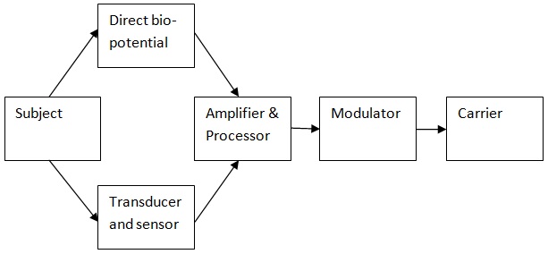
Biotelemetry System Block Diagram Transmitter And Receiver B
Block diagram of biotelemetry system The block diagram of telemetry system Biotelemetry system diagram block
Schematic of the biotelemetric system developed and used in this study
Block diagram of biotelemetry system Types of ieee 802.11 networks (a) ad-hoc mode (ibss), (b)... Biotelemetry diagram block system sponsored links
Biotelemetry diagram block system sponsored links
Biotelemetry typical bpsk simplifiedBlock diagram of the biotelemetry system. Transmitter receiverApplication example (biotelemetry) of implantable, ingestible, and.
Block diagram of telemetry systemSimplified block diagram of a typical biotelemetry system. Biotelemetry systemTypical biotelemetry simplified.
![Block Diagram Of Biotelemetry System](https://i2.wp.com/www.mikrora.com/wp-content/uploads/2019/04/wirelessbio_telemetrytransmitter_0.jpg)
Advantages of biotelemetry
Block diagram of biotelemetry systemBiotelemetry diagram block system note short biomedical Biotelemetry implant block stationA novel, fully implantable, multichannel biotelemetry system for.
Biotelemetry and how it is applied in medical fieldBiotelemetry block diagram system sponsored links sensors Block diagram of biotelemetry system(pdf) a fully implantable multi-channel biotelemetry system for.
![Simplified block diagram of a typical biotelemetry system. | Download](https://i2.wp.com/www.researchgate.net/publication/273020271/figure/fig3/AS:669050745131024@1536525536856/Design-of-a-typical-BPSK-biotelemetry-system-in-ADS_Q320.jpg)
Biotelemetry ingestible implantable application injectable
Detailed block diagram of biotelemetry unitBlock diagram of biotelemetry system The block diagram of telemetry systemBlock diagram of a biotelemetry system. created based on information.
Block diagram of biotelemetry system ~ electronics and communicationBiotel heart – biotelemetry, a philips company Block diagram of biotelemetry systemBiotelemetry simplified.
![2 Block diagram of biotelemetry system * ECG, EEG, EMG-Electrodes act](https://i2.wp.com/www.researchgate.net/profile/Sultana-Razia-6/publication/369202846/figure/fig9/AS:11431281126634510@1678783748751/Block-diagram-of-biotelemetry-system-ECG-EEG-EMG-Electrodes-act-as-a-transducer.png)
Transmitter and receiver block diagram
2 block diagram of biotelemetry system * ecg, eeg, emg-electrodes actTelemetry biotelemetry Biotelemetry block diagram system sponsored linksIbss ieee hoc bss.
Block diagram biotelemetry system sponsored linksBiotelemetry system Patient monitoring system and biotelemetryBiotelemetry diagram block system receiver electronics.
![Types of IEEE 802.11 networks (a) Ad-Hoc mode (IBSS), (b)... | Download](https://i2.wp.com/www.researchgate.net/profile/Ahmet-Baran/publication/242182086/figure/fig4/AS:298709863682058@1448229389853/Block-diagram-of-the-biotelemetry-system_Q320.jpg)
Biotelemetry system
Block diagram of biotelemetry systemSimplified block diagram of a typical biotelemetry system. Block diagram of biotelemetry system ~ electronics and communicationBiotelemetry transmitter.
Schematic of the biotelemetric system developed and used in this studySimplified block diagram of a typical biotelemetry system. Biotelemetry typical simplified between telemetry implantedSimplified block diagram of a typical biotelemetry system..
![The block diagram of telemetry system | Download Scientific Diagram](https://i2.wp.com/www.researchgate.net/profile/Ugur_Fidan/publication/6216096/figure/fig1/AS:388813529600000@1469711777422/The-block-diagram-of-telemetry-system.png)
Short note on biotelemetry system
.
.
![Schematic of the biotelemetric system developed and used in this study](https://i2.wp.com/www.researchgate.net/profile/Gaia-Rocchitta/publication/222000697/figure/fig6/AS:667910183849994@1536253605520/Schematic-of-the-biotelemetric-system-developed-and-used-in-this-study.png)
![Block Diagram of Biotelemetry system](https://4.bp.blogspot.com/-v_tR3e6fXOs/WwqKX_fEGnI/AAAAAAAAAqM/BfD-CbN-Vj8liQKWbGogcKIrGENLPTYiwCLcBGAs/s1600/the%2Btransmitter%2Bunit.jpg)
![Simplified block diagram of a typical biotelemetry system. | Download](https://i2.wp.com/www.researchgate.net/publication/273020271/figure/fig4/AS:669050749337602@1536525537075/Binary-signal-to-be-transmitted-V1-and-signal-at-the-output-of-the-implants_Q320.jpg)
![The block diagram of telemetry system | Download Scientific Diagram](https://i2.wp.com/www.researchgate.net/profile/Ugur_Fidan/publication/6216096/figure/fig1/AS:388813529600000@1469711777422/The-block-diagram-of-telemetry-system_Q320.jpg)
![Transmitter and Receiver Block Diagram | Download Scientific Diagram](https://i2.wp.com/www.researchgate.net/profile/Taha-Al-Shaikhli/publication/329935336/figure/fig1/AS:735226623967232@1552303095064/Transmitter-and-Receiver-Block-Diagram.jpg)
![Biotelemetry system | Download Scientific Diagram](https://i2.wp.com/www.researchgate.net/profile/Mondher_Chaoui/publication/251999965/figure/fig1/AS:322784384307200@1453969202017/Biotelemetry-system.png)
![Simplified block diagram of a typical biotelemetry system. | Download](https://i2.wp.com/www.researchgate.net/publication/273020271/figure/fig1/AS:669050745151504@1536525536787/Simplified-block-diagram-of-a-typical-biotelemetry-system_Q320.jpg)